 Electronics")
Zigbee Mesh Network Relay
Our relay boards can work with all xbee modules. Some of the people want build a zigbee mesh network to control these relay boards. But they don't know how to do it. This instructions will use the simplest several steps to guide you.
XBee are popular wireless modules used by hobbyists and DIYers. These wireless modules come in variety of styles and power ratings (distance ranges). There are several tutorials even instructables for configuring XBees for point-point (P2P) communication. P2P communication is restricted between two end-points and this is all you need if you only have two wireless devices in your setup. What do you if you have multiple devices...say a network? Perhaps we should start with a simpler setup.
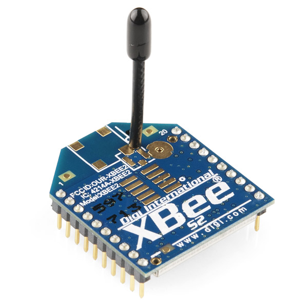
In this instructable, I will show you how to configure XBees for a zigbee mesh. You should choose a XBee S2 series module.
In this configuration, there will be one central COORDINATOR and multiple ROUTERS. The ROUTER will send and receive messages from the COORDINATOR and the COORDINATOR will have to sort which wireless packets came from which ROUTER and send packets to the appropriate ROUTER as well.
STEP1: Hardware and Software
- Download X-CTU6.2 and install it
- XBee S2 module x3
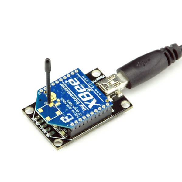
- XBee USB adapter x2
- 4 Channel USB relay board x2
- 5V power supply x2
STEP2: Wireless Setup
The XBee S2 modules can be configured in two ways: Transparent Mode (AT) and API Mode (API). In AT mode you are limited to point-to-point communication between two XBees. In API mode, we can trivally send and receive from both the COORDINATOR and many many XBees out in the world. Additionally, API mode will expose a variety of additional information encoded in each packet. Here we need set the COORDINATOR to API mode(Connect with your computer). and 2 XBees on the relay(ROUTER) to AT mode.
2.1 Plug one XBee on USB adapter and connect it to your computer USB port, install the FTDI drivers and a new USB port will appears in your device manager.
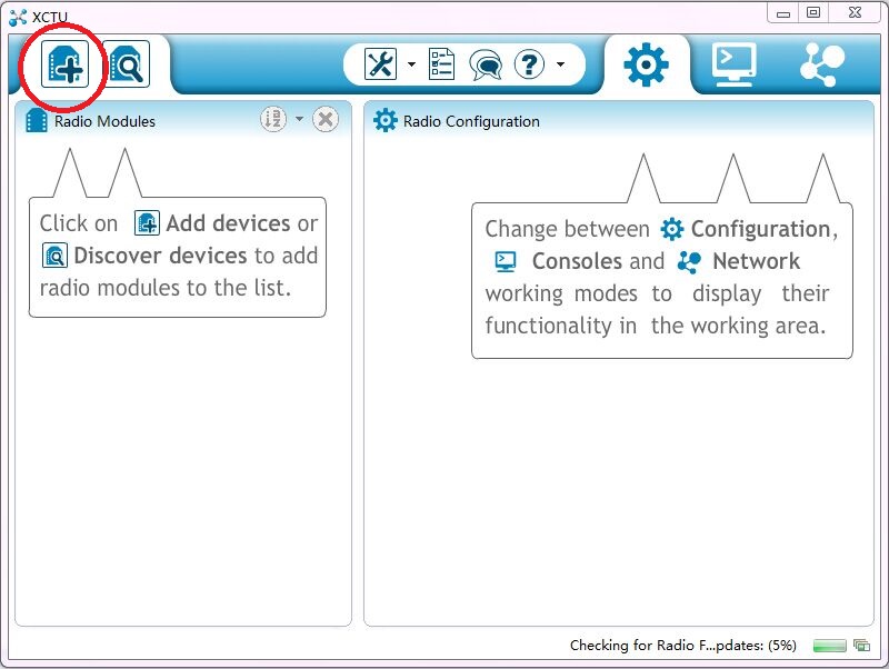
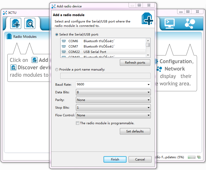
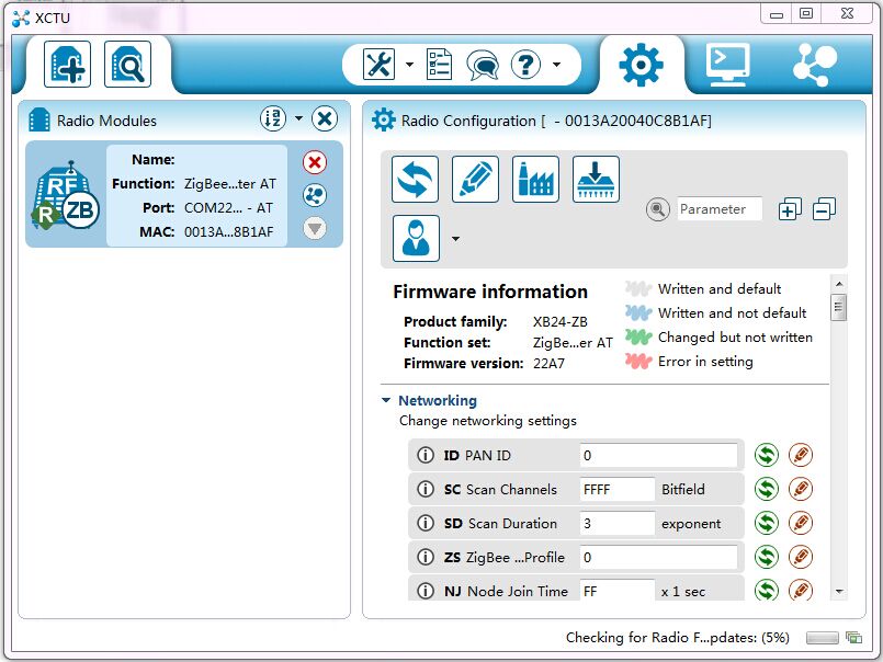
2.2 Open X-CTU, "Add a radio module specifying the port setting"->select the correct COM port.
2.3 Click the module to read the module info.
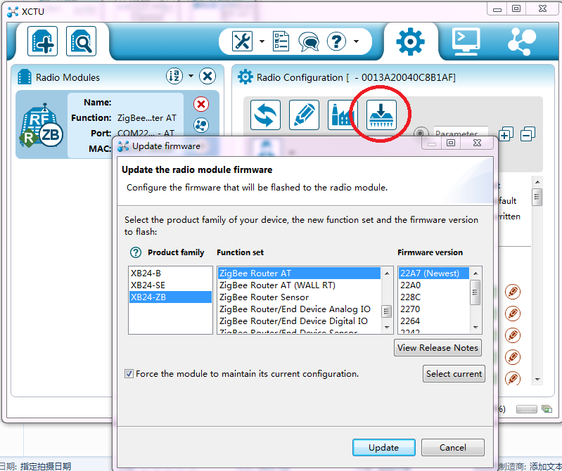
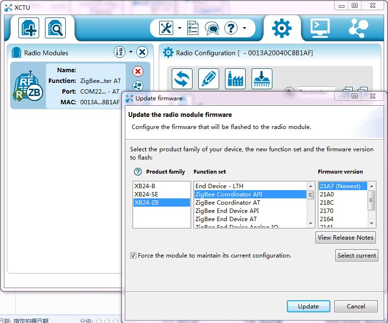
2.4 Update firmware->change the module firmware to "Zigbee Coordinator API"
2.5 Plug another XBee on a USB adapter and connect it to your computer another USB port, find it on X-CTU.
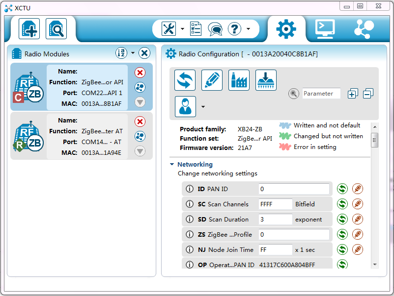
2.6 Make sure the module firmware are "Zigbee Router AT". and the OI value are same as COORDINATOR module.
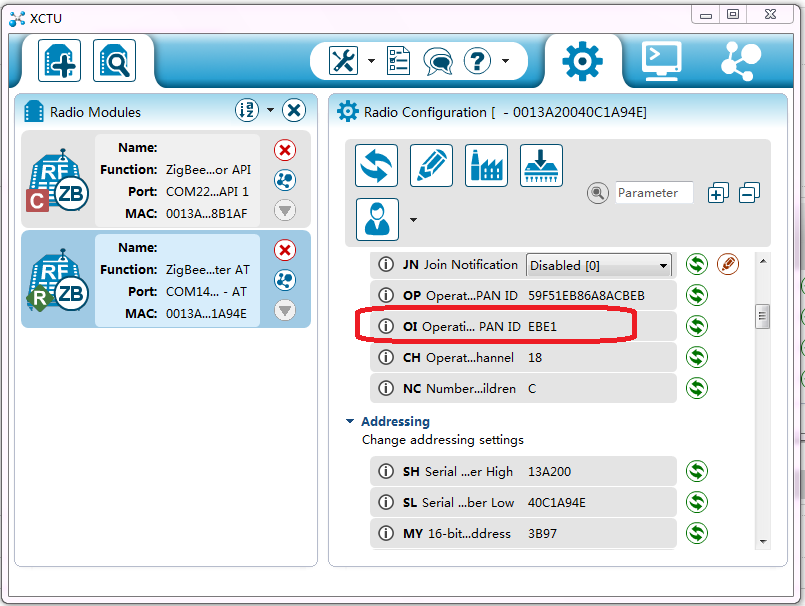
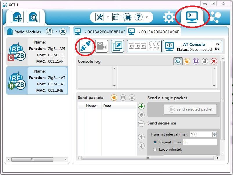
2.7 If the OI are same. Just skip this step. If it's different. Switch to consoles working mode->open the serial connection with the radio module.
Input AT commands
+++
ATNR
Enter
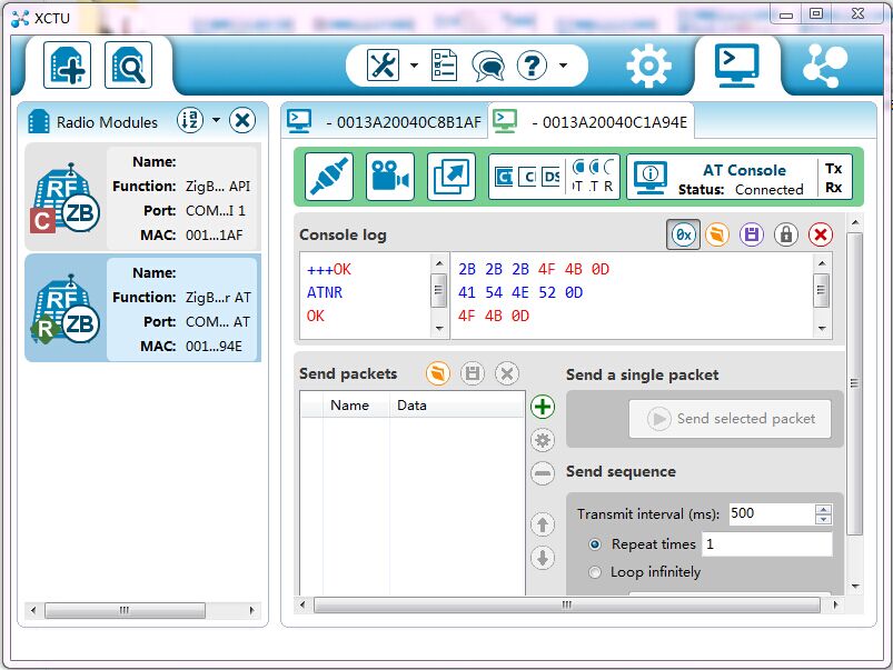
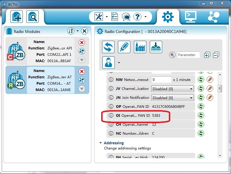
Swtich back to Configuration working mode->refresh radio settings, You will find the OI value same as COORDINATOR now.
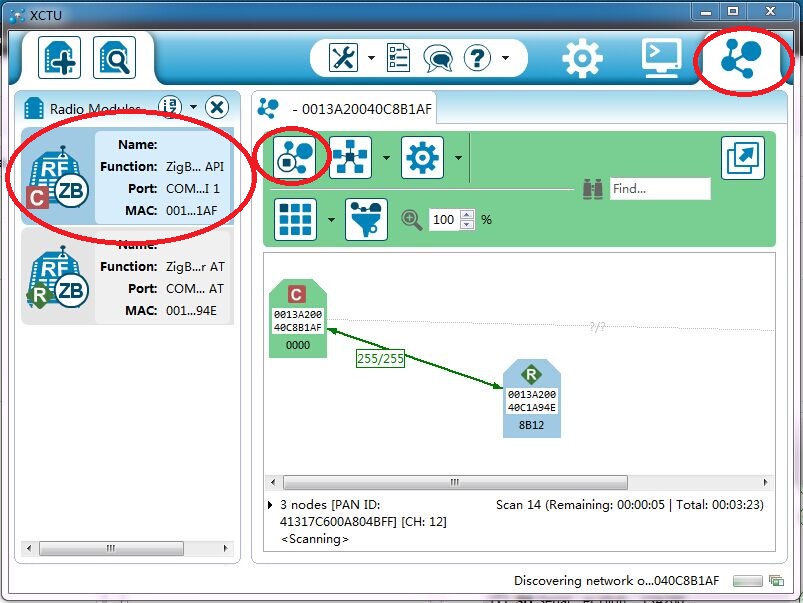
2.8 Select COORDINATOR module->Switch to network working mode->Scan the radio module network. You will find these 2 modules build a simple zigbee network. Repeat the same steps to configure the XBee module 3. these 3 modules will build a simple mesh network.
Remember the Router module address, Here the address is 00 13 A2 00 40 C1 A9 4E
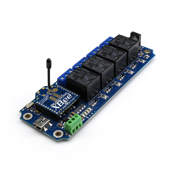
STEP3: Relay control
Plug these 2 Router XBee modules on relay boards. You can control it by send commands now.
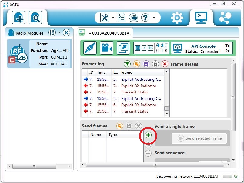
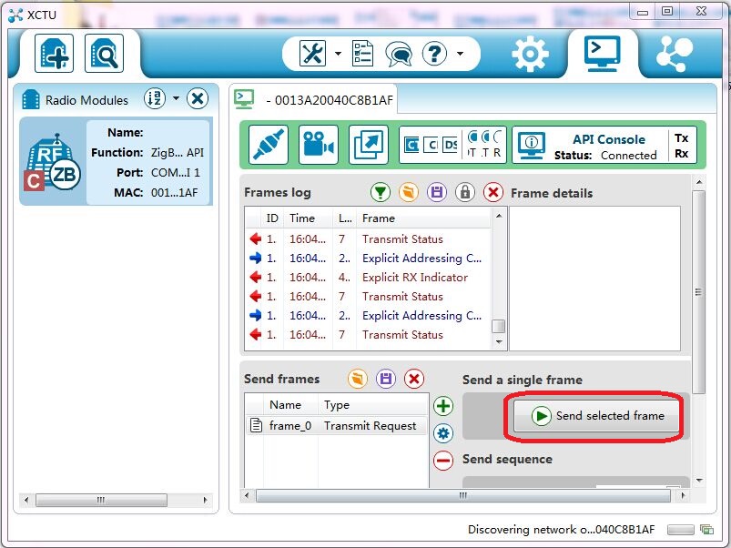
Select COORDINATOR module->Switch to consoles working mode->open the serial connection with the radio module->add new frame to the list
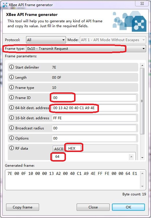
A sample command: Turn all relay ON. The command is 0x64, Use Frame Generator creat a command frame.
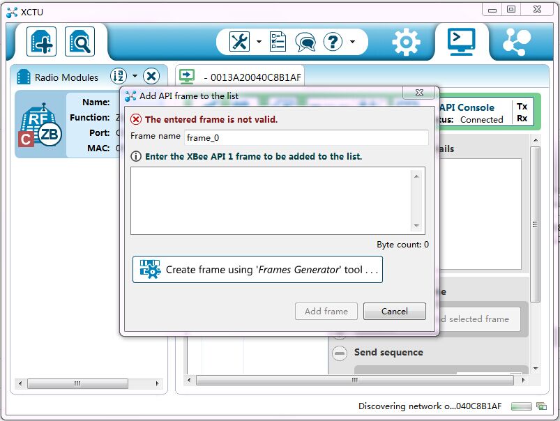
Frame type: 0x10
Frame ID: 0x00
Dest address: The router module address
RF data: 0x64
Slect the frame->Send selected frame. You will see all the relay turn ON.
This is just a simple guide of how to bulid a zigbee mesh network relay. You can add many zigbee router relays in this zigbee mesh network. It's very useful for your zigbee home automation system.